Electrode placement induced brain shift#
In case of electrode placement-induced brain shift, we constructed an electrode sheet in order to select the underlying brain nodes on which displacements are applied. The procedure begins with selecting original electrode positions from intra-operative CT and is divided into following steps:
Select the “ElectrodesToMarkups” module (see Fig. 1.25{reference-type=”ref” reference=”fig:electrode”}).
Select the “Input Electrode” image, which is a “.nrrd” image with segmented electrodes from intra-operative CT.
Select the “Minimum Size (Split island)”, which is the size of the number of voxels that defined a single electrode.
Select the “Save Electrode Centroid Positions”, which is the .txt file for saving the x,y,z coordinates for each electrode or (save the fiducials file .fcsv, which are the generated red dots placed at the identified location for each electrode).
Hit “Apply”
The results is the Markups/fiducials (red dots). The file of which can be saved separately as .fcsv file.
 {#fig:electrode_2 width=”\textwidth”}
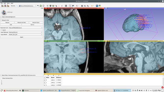
After you get the fiducials (red dots = identified original electrode locations), we use these to identify the projected electrode locations (the position of each of the electrode on an undeformed brain surface). We use the “fiducialtomodeldistance” (see Fig. 1.26{reference-type=”ref” reference=”fig:electrode_2”}) for this purpose, the steps are as follows:
Select the “fiducialtomodeldistance” module.
Select the “Input Markups”, which are the identified original electrodes represented by the fiducials (red dots).
Select the “Input Model”, which is the patient-specific triangulated surface model.
Hit “Apply”
The result is the set of fiducials representing the projected electrode locations on the brain surface.
 {#fig:electrode_3 width=”\textwidth”}
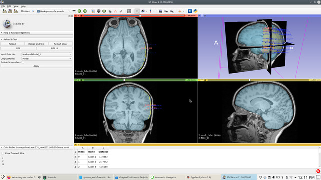
After getting the projected electrode locations, we construct an electrode sheet model using the information of the locations of the projected electrodes on the brain surface (see Fig. 1.27{reference-type=”ref” reference=”fig:electrode_3”}). The steps are as follows:
Select “Markupstosurfacemesh” module.
Select the “Input fiducials”, which are the projected electrode locations.
Select the “Output Model”, which is the resulting electrode sheet model.
Hit “Apply”, to get the electrode sheet model as in Fig. 1.27{reference-type=”ref” reference=”fig:electrode_3”}.
 {#fig:electrode_4 width=”\textwidth”}
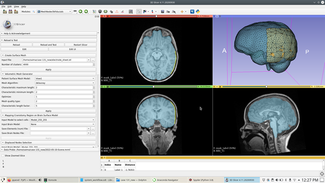
After getting the electrode sheet surface model, we do the uniform triangulation of the electrode sheet surface by using the “SurfaceTriangulation” (see Fig. 1.28{reference-type=”ref” reference=”fig:electrode_4”}). The steps are as follows:
Select the “SurfaceTriangulation” module.
Select the “Input Model”, which is the electrode sheet surface model.
Select the “Number of clusters”.
Hit “Apply”, to get a uniform surface triangulation of the electrode sheet with clusters of your choice.
 {#fig:electrode_5 width=”\textwidth”}
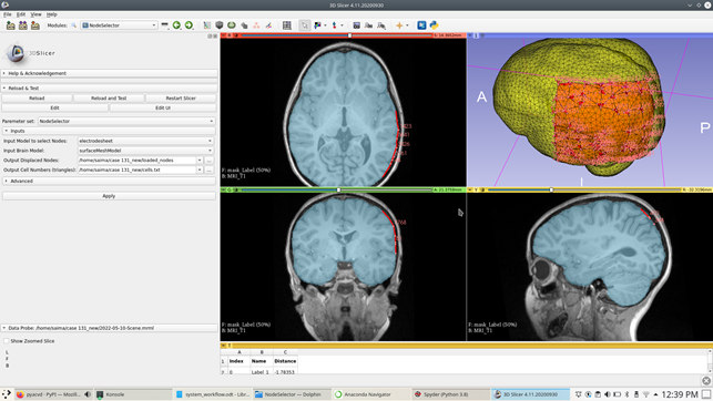
After constructing a triangulated electrode sheet model, we use it to select the underlying brain cells and then from there we select the corresponding brain nodes (loaded nodes). The steps are as follows:
Select the “NodeSelector” module (see Fig. 1.29{reference-type=”ref” reference=”fig:electrode_5”}).
Select the “Input model to select Nodes”, which is the reference model to select the brain surface nodes i.e; electrode sheet model.
Select the “Input Brain Model”, the brain model on which the loaded nodes are selected.
Select “Output Displaced Nodes”, which is the .txt file of the selected nodes under electrode sheet model.
Select “Output Cell Numbers (triangles)”, which is the .txt file of the selected brain cells under electrode sheet model.
Hit “Apply”, gives you the corresponding brain nodes with fiducials placed at each selected brain node (see Fig. 1.29{reference-type=”ref” reference=”fig:electrode_5”}).
 {#fig:electrode_6
width=”\textwidth”}
{#fig:electrode_6
width=”\textwidth”}
![Displacement loading calculation based on undeformed and deformedbrain surface nodes (seeFig. [fig:electrodes_8]{reference-type="ref"reference="fig:electrodes_8"})](../../_images/electrode_7.png) {#fig:electrode_7 width=”\textwidth”}
{#fig:electrode_7 width=”\textwidth”}
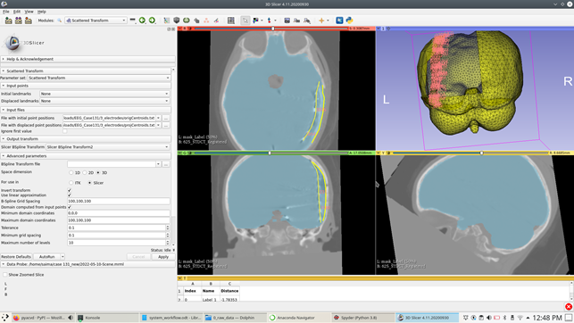
We then used the original electrode locations and projected electrode locations to calculate a transform using scattered transform. We use this transform and apply it on the selected brain nodes (loaded nodes) on the brain surface to get the brain nodes on the deformed brain surface. The steps to calculate the B-spline transform using the scattered transform are as follows:
Select the “Scattered Transform” module.
Select the “File with initial point positions”, which is the locations of the original electrode positions.
Select the “File with displaced point positions”, which is the locations of the projected electrode positions.
Select “Slicer B-spline transform”.
Leave all other settings remain unchanged and hit “Apply”, the result is a transform.
Use the transform module to apply on the brain nodes (loaded nodes) to get the corresponding brain nodes locations on the deformed brain geometry (see Fig. 1.30{reference-type=”ref” reference=”fig:electrode_6”} and 1.31{reference-type=”ref” reference=”fig:electrode_7”}).
We then do load calculation using the displacement loading in “MeshNodesToFiducials” module (see Fig. 1.31{reference-type=”ref” reference=”fig:electrode_7”} and 1.32{reference-type=”ref” reference=”fig:electrode_8”}).
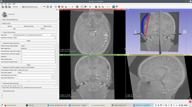 {#fig:electrode_8 width=”\textwidth”}
In case of non-rectangular electrode grid, the selection of displaced nodes is done using the “BrainMeshSurfaceCellsSelection” (see Fig. 1.33{reference-type=”ref” reference=”fig:brainCells”} and 1.34{reference-type=”ref” reference=”fig:neighbourCells”}) “BrainSurfaceNeighbouringCellsSelection” modules.
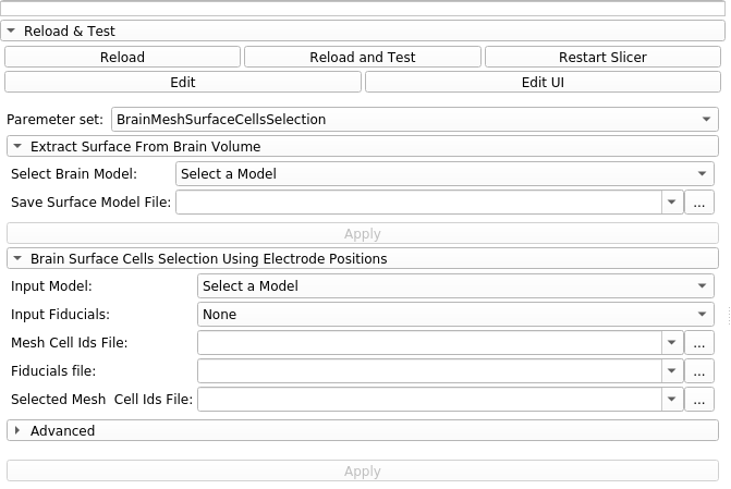 {#fig:brainCells width=”\textwidth”}
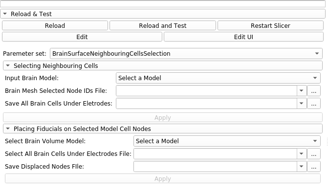 {#fig:neighbourCells width=”\textwidth”}