Craniotomy-induced brain shift#
Authors: Saima Safdar
For craniotomy-induced brain shift, we need a craniotomy region to select the nodes under the craniotomy area on the brain surface. For this we created a module to automatically construct that craniotomy region (see Fig. 1.19{reference-type=”ref” reference=”fig:cran”}). The steps are as follows:
Select the “CranCreator” module.
Select the “Input volume” to create a head mask for pre-operative MRI.
Hit “Apply” to generate the preoperative head mask.
Select the “Input volume” to create a head mask using intra-operative MRI.
Hit “Apply” to generate the intraoperative head mask.
Select the “Select preoperative segment”, which is the head segment generated in step 3.
Select the “Select intraoperative segment”, which is the head segment generated in step 5.
Hit “Apply” to get the craniotomy region.
 {#fig:cran_2dmodel
width=”\textwidth”}
{#fig:cran_2dmodel
width=”\textwidth”}
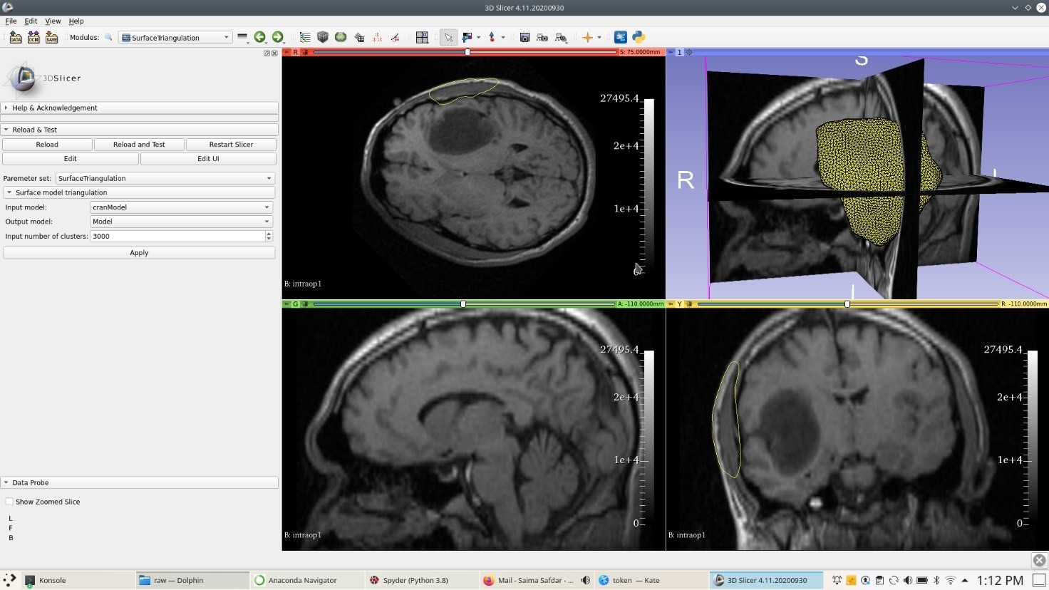
Generate the surface model for this craniotomy region using “Model Maker” module of 3D Slicer. After generating a craniotomy surface model, generate a uniform triangulation of the craniotomy surface model using the “SurfaceTriangulation” module (see Fig. 1.20{reference-type=”ref” reference=”fig:cran_2dmodel”}).
 {#fig:node_sel
width=”\textwidth”}
{#fig:node_sel
width=”\textwidth”}
 {#fig:node_sel2 width=”\textwidth”}
 {#fig:node_sel3 width=”\textwidth”}
 {#fig:node_sel4 width=”\textwidth”}
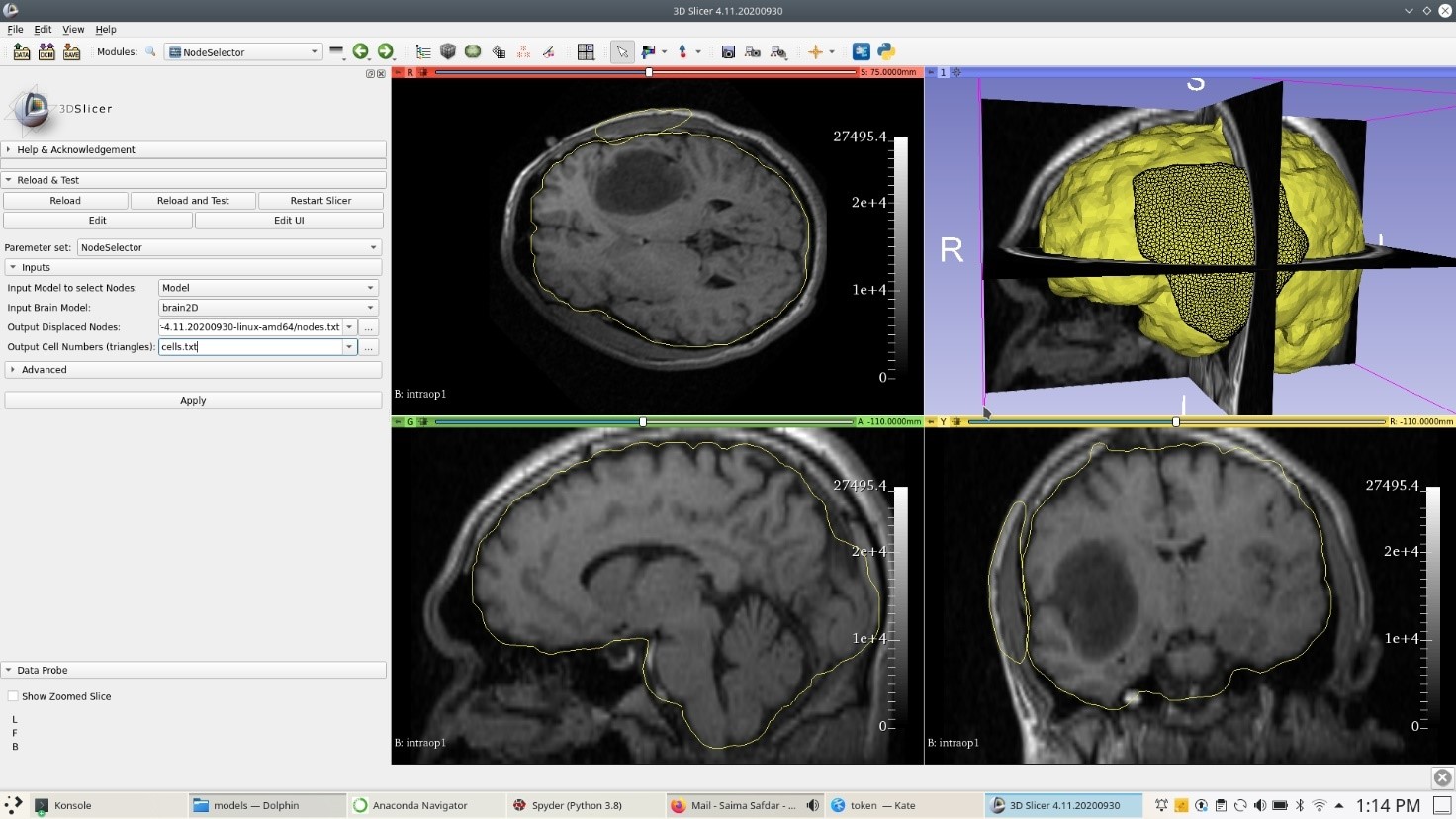
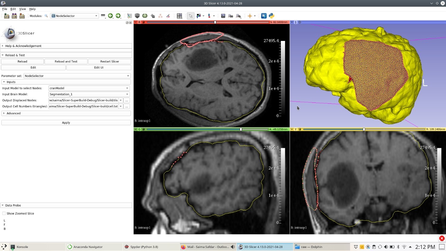
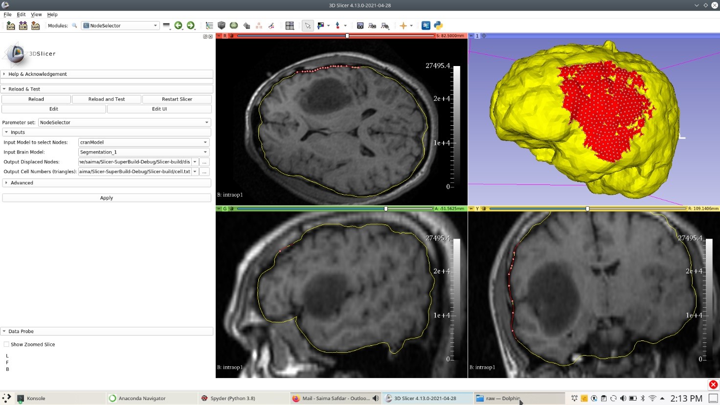
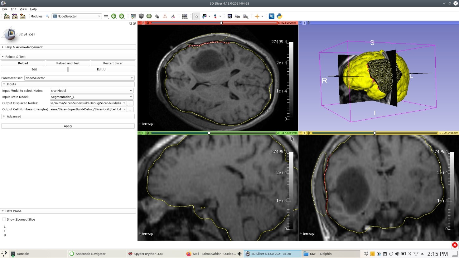
Use the “NodeSelector” to select the brain surface nodes under craniotomy region (see Fig. 1.21{reference-type=”ref” reference=”fig:node_sel”}). The steps are as follows:
Select the “NodeSelector” module.
Select the “Input Model to select Nodes”, which is the craniotomy region model.
Select the “Input Brain Model”, which is the patient-specific brain surface triangulated model.
Select the “Output Displaced Nodes”, which is the txt file to save the loaded nodes ids.
Select the “Output Cell Numbers (Triangles)”, which is the txt file containing cell numbers.
Hit “Apply” to get the selected brain nodes (loaded nodes), on which displacements will be applied.
The result for the “NodeSelector” are in Fig. 1.22{reference-type=”ref” reference=”fig:node_sel2”}.
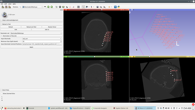 {#fig:electrode width=”\textwidth”}